COMPLIANCE TO SAFETY STANDARDS
The OIL STOP has been designed and manufactured in accordance with the laws and standards set forth by the American Conference Governmental Industrial Hygienists (ACGIH). The OIL STOP meets or exceeds the T.V.L. (Threshold Limit Values) and T.W.A. (Time-Weighted Average) for the maximum acceptable concentration of the different polluting substances (for machine tools mist the maximum value is 5 mg/m3.).
MAXIMUM EFFICIENCY
The OIL STOP performs with a very high level of filtration efficiency (up to 99%). Where bad oder must also be removed, OIL STOP is equipped optionally with CARBO activated charcoal filters. If oders are to be removed the composition of the polluting agents should be supplied to enable us to suggest the proper activated charcoals.
QUIET OPERATION
Due to the layout of its filters, their remarkable absorbing power and the special streamline, the OIL STOP can be used in any environment without causing acoustic pollution. Where very low noise levels are required, OPTIONAL AFON model silencers are supplied.
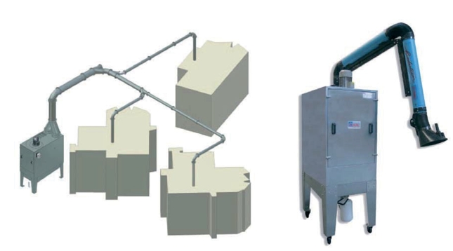
OPTIONS
Depending on the different requirements, OIL STOP can be supplied with CARBO charcoal filters, with absolute filters or with any other type of filter to solve potential problems. As an option we can supply either a collection tank or a continuous oil drainage system, and, in case of special installation requirements, also high-pressure PA/P - PR - AP/T - PR/T - VAP.
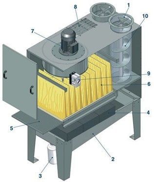 1. Oil mist air inlet
2. Oil drain hooper
3. Oil collecting tank
4. Drop separator (Optional)
5. Wire metal mesh prefilter
6. Pocket filter
7. Fan
8. Clean air outlet
9. Thermal switch
10. Centrifugal separator
Operating Principle
Contaminated air with heavy oil mist from the machine application enters the OIL STOP and passes through the first stage centrifugal/mechanical separating chamber, which is composed by a helical system and a metal screen The centrifugal inlet chamber has the same cross section as the intake opening thereby reducing pressure drop. Due to the centrifugal force created by the air speed inside the centrifugal separator, the heavy mist impacts the helical insert and separates from the air. The screen in the chamber prevents its reinterring back into the air flow and drives them to slide along the walls of the chamber and fall below by gravity, onto the oil collection hopper. Oil is then collected in a small tank and recycled if required. A large portion of the oil droplets in suspension at this point have been separated, and the air now passes through the drop separator (Optional) and the wire metal mesh pre-filter. Due to the efficient operation of these three levels of filtration, all oil mist has been removed from the air stream to further remove any possible remaining impurities, like micro mists and oil vapors, the air passes through a final high efficiency pleated pocket filter, which is made of ultra fine glass fiber filtering material. The high-quality pleated filter cartridge contains a large volume of surface area for long life. The air is finally exhausted through the discharge grate located on the top of the OIL STOP.
Dimensions
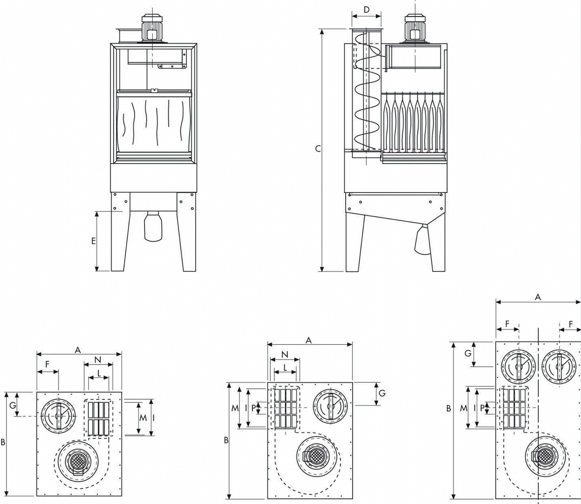
OIL STOP 1 OIL STOP 2 OIL STOP 3
| Dimensions | Model | A | B | C | D | E | F | G | 1 | L | M | N | P | |||
| OILSTOP1 | 700 | 1060 | 1750 | 220 | 480 | 207 | 235 | 257 | 164 | 225 | 194 | - | ||||
| OILSTOP2 | 700 | 1060 | 1750 | 280 | 480 | 207 | 235 | 360 | 206 | 385 | 230 | 135 | ||||
| OILSTOP4 | 700 | 1450 | 1750 | 2x280 | 480 | 177,5 | 205 | 401 | 224 | 430 | 250 | 270 | ||||
Technical Specifications
| Code | 50920100 | 50920200 | 50920400 | 50920500 | |||
| OILSTOP | OILSTOP 1 | OILSTOP2 | OILSTOP4 | Universal No Somke | |||
| Maximum Airflow | 1315 m³/h | 2530 m³/h | 3600 m³/h | 1470 m³/h | |||
| Power | 0,75 kW | 1,5 kW | 3kW | 1,5 kW | |||
| Voltage | 230/400 V | 230/400 V | 230/400 V | 230/400 V | |||
| 3 phase 50 Hz | 3 phase 50 Hz | 3 phase 50 Hz | 3 phase 50 Hz | ||||
| Rpm | 2800 | 2800 | 2800 | 2800 | |||
| Noise Level (without silencer) | 74 dB (A) | 76 dB (A) | 83 dB (A) | 79 dB (A) | |||
| Gross Weight | 145 kg | 192 kg | 245 kg | 213 kg | |||
| Filter Efficiency | %99 | %99 | %99 | %99 | |||
| Inlet Diameter | Ø220 mm | Ø280 mm | 2xØ280 mm | Ø150 mm | |||
| Outlet Dimensions | 164x257 mm | 206x360 mm | 224x401 mm | 206x360 mm | |||
| Bin | 5 Lt | 5 Lt | 10 Lt | 5 Lt | |||